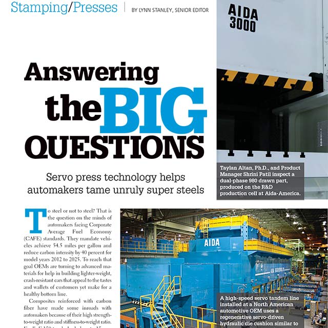
High Speed Press MSP Multiple Suspension Point, From 220 - 400 Tons

Press Information
Press Information & Overview
High Speed, High Precision Motor Core Lamination Press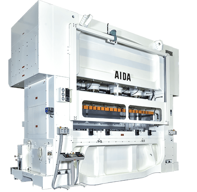
With the MSP high speed stamping press, dynamic accuracy is significantly improved because of the compact design and multiple suspension points.
A balance between high rigidity and a wide bed area is brought to a higher level using the latest technology.
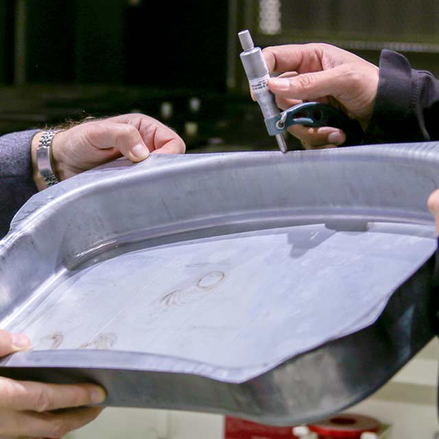
Ultra precision dies require a large bed area for the production of high-efficiency motors, such as motors for hybrid cars or for energy conservation. Responding to these needs, AIDA applied innovative new technology to achieve increased precision with the AIDA MSP Series High Speed Stamping Press.
Press Features
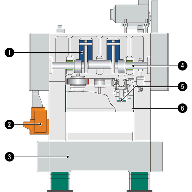
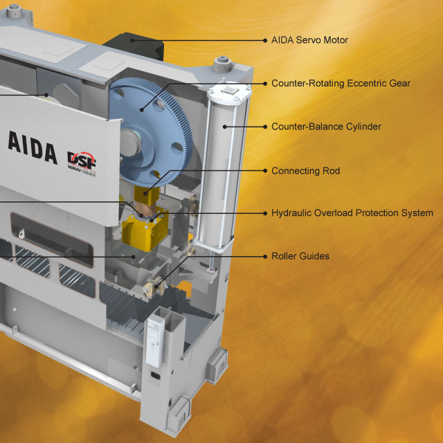
AIDA MSP High Speed Press Features
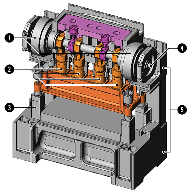
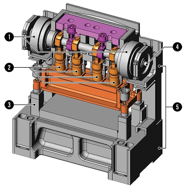
- Twin Drive
- Multiple Suspension
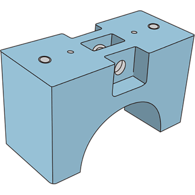
- Highly Rigid Guidepost
- Clutch & Brake
- Highly Rigid Frame
Bottom Dead Center (BDC) Compensation
 Stabilizing Punch Penetration Over Time
Specially designed suspension points allow for in process BDC adjustment to maintain the desired setting and can be done automatically as often as every 100 press strokes
Combined Bearings
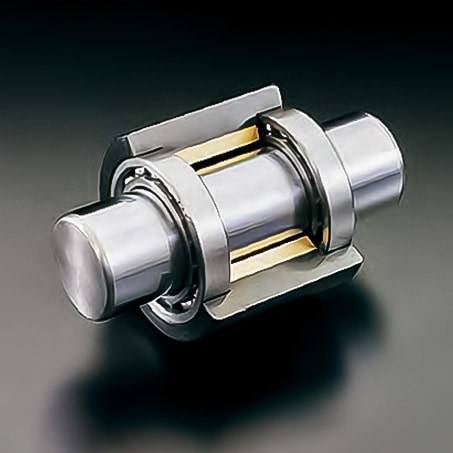 Roller and Oil Film Bearings Housed in a Single Unit
Controls BDC variations casued by speed change. In high speed presses the bottom dead center position of the slide will change as the press speed goes up or down
Dynamic Balancing
 Stabilizes Press Structure by Balancing Inertia Forces in High Speed Operations
Inertia forces generated by the slide and upper die can cause the press to become unstable. Balancing of these forces is accomplished by installing a large weight (or weights) that reciprocate exactly opposite the slide and upper die.
Eccentric Shaft Drive
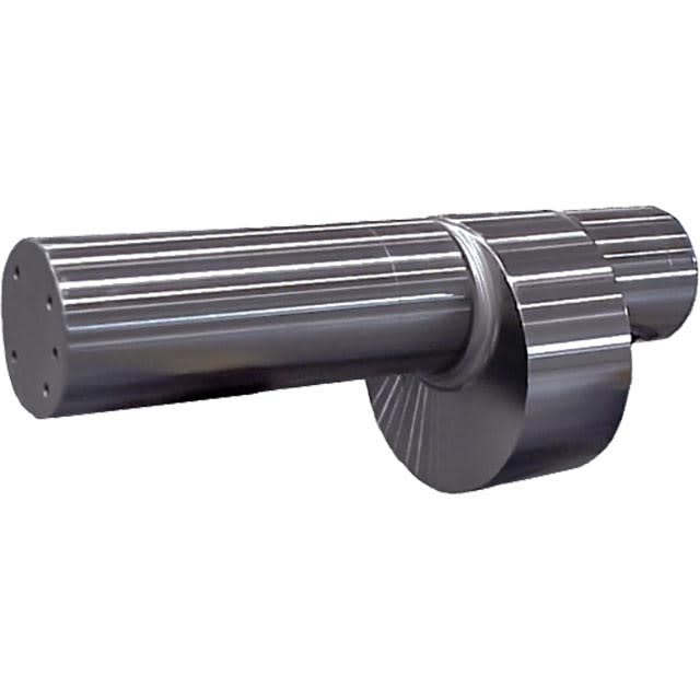 Ideal for Short Stroke Precision Stamping Operations
Eccentric shafts are used primarily in high speed and progressive die stamping operations. Allows for placement of bearing supports against both sides of the eccentrics.
Thermal Control
 Circulating Temperature Controlled Oil to Every Moving Part of the Press
To control thermal expansion and reduce its effect on your final parts, AIDA stamping presses employ a system that circulates temperature controlled oil (via an external cooling system if necessary) to every moving part in the press and feed.
Press Specifications
MSP High Speed Press Specifications
| 220 Ton, 2,000 mm Bed |
| 300 Ton, 2,300 mm Bed |
| 300 Ton, 2,700 mm Bed |
| 300 Ton, 3,300 mm Bed |
| 300 Ton, 3,700 mm Bed |
| 400 Ton, 2,800 mm Bed |
| 400 Ton, 3,300 mm Bed |
| 220 - 400 Ton |
MSP-2200, 220 Ton High Speed Press Press Specifications
| MSP MODELS | ||||||||
| Press Technical Data | Unit | MSP-2200-200 | ||||||
| No. of Points | 3 | |||||||
| Tonnage Capacity | kN | 2200 | ||||||
| U.S. Ton | 250 | |||||||
| Rated Tonnage Point | mm | 3.2 | ||||||
| in. | 0.13 | |||||||
| Stroke Length | mm | 30 | ||||||
| in. | 1.18 | |||||||
| Continuous Working Energy | J | 2000 | ||||||
| in.-ton | 9 | |||||||
| Strokes Per Minute No Load | spm | 120 - 500 | ||||||
| Micro Inching | spm | 60 | ||||||
| Die Height | mm | 420 - 480 | ||||||
| in. | 16.54 - 18.9 | |||||||
| Slide Adjustment | mm | 60 | ||||||
| in. | 2.36 | |||||||
| Slide Area | mm | 2000 x 800 | ||||||
| in. | 78.74 x 31.5 | |||||||
| Bolster Area | mm | 2000 x 1000 | ||||||
| in. | 78.74 x 39.37 | |||||||
| Bolster Thickness | mm | 200 - 260 | ||||||
| in. | 7.87 - 10.24 | |||||||
| Max. Upper Die Weight | kg | 1800 | ||||||
| lb. | 3968 | |||||||
| Side Opening | mm | 490 | ||||||
| in. | 19.29 | |||||||
| Bed Hole Dimension | mm | 1700 x 400 | ||||||
| in. | 66.93 x 15.75 | |||||||
| Main Motor | kW | 45 | ||||||
| HP | 60 | |||||||
| Required Air Pressure | MPa | 0.5 | ||||||
| psi | 73 | |||||||
MSP-3000-2300, 300 Ton, 2300 mm Bed, High Speed Press Press Specifications
| MSP MODELS | ||||||||
| Press Technical Data | Unit | MSP-3000-230 | ||||||
| No. of Points | 3 | |||||||
| Tonnage Capacity | kN | 3000 | ||||||
| U.S. Ton | 330 | |||||||
| Rated Tonnage Point | mm | 3.2 | ||||||
| in. | 0.13 | |||||||
| Stroke Length | mm | 30 | ||||||
| in. | 1.18 | |||||||
| Continuous Working Energy | J | 3000 | ||||||
| in.-ton | 13 | |||||||
| Strokes Per Minute No Load | spm | 120 - 450 | ||||||
| Micro Inching | spm | 60 | ||||||
| Die Height | mm | 420 - 520 | ||||||
| in. | 16.54 - 20.47 | |||||||
| Slide Adjustment | mm | 60 | ||||||
| in. | 2.36 | |||||||
| Slide Area | mm | 2300 x 800 | ||||||
| in. | 90.55 x 31.5 | |||||||
| Bolster Area | mm | 2300 x 1000 | ||||||
| in. | 90.55 x 39.37 | |||||||
| Bolster Thickness | mm | 210 - 260 | ||||||
| in. | 8.27 - 10.24 | |||||||
| Max. Upper Die Weight | kg | 2000 | ||||||
| lb. | 4409 | |||||||
| Side Opening | mm | 490 | ||||||
| in. | 19.29 | |||||||
| Bed Hole Dimension | mm | 2000 x 400 | ||||||
| in. | 78.74 x 15.75 | |||||||
| Main Motor | kW | 55 | ||||||
| HP | 74 | |||||||
| Required Air Pressure | MPa | 0.5 | ||||||
| psi | 73 | |||||||
MSP-3000-2700, 300 Ton, 2700 mm Bed, High Speed Press Press Specifications
| MSP MODELS | ||||||||
| Press Technical Data | Unit | MSP-3000-270 | ||||||
| No. of Points | 3 | |||||||
| Tonnage Capacity | kN | 3000 | ||||||
| U.S. Ton | 330 | |||||||
| Rated Tonnage Point | mm | 3.2 | ||||||
| in. | 0.13 | |||||||
| Stroke Length | mm | 30 | ||||||
| in. | 1.18 | |||||||
| Continuous Working Energy | J | 3000 | ||||||
| in.-ton | 13 | |||||||
| Strokes Per Minute No Load | spm | 100 - 420 | ||||||
| Micro Inching | spm | 60 | ||||||
| Die Height | mm | 470 - 520 | ||||||
| in. | 18.5 - 20.47 | |||||||
| Slide Adjustment | mm | 60 | ||||||
| in. | 2.36 | |||||||
| Slide Area | mm | 2700 x 800 | ||||||
| in. | 106.3 x 31.5 | |||||||
| Bolster Area | mm | 2700 x 1000 | ||||||
| in. | 106.3 x 39.37 | |||||||
| Bolster Thickness | mm | 250 - 300 | ||||||
| in. | 9.84 - 11.81 | |||||||
| Max. Upper Die Weight | kg | 2300 | ||||||
| lb. | 5071 | |||||||
| Side Opening | mm | 490 | ||||||
| in. | 19.29 | |||||||
| Bed Hole Dimension | mm | 2400 x 400 | ||||||
| in. | 94.49 x 15.75 | |||||||
| Main Motor | kW | 55 | ||||||
| HP | 74 | |||||||
| Required Air Pressure | MPa | 0.5 | ||||||
| psi | 73 | |||||||
MSP-3000-3300, 300 Ton, 3300 mm Bed, High Speed Press Press Specifications
| MSP MODELS | ||||||||
| Press Technical Data | Unit | MSP-3000-330 | ||||||
| No. of Points | 4 | |||||||
| Tonnage Capacity | kN | 3000 | ||||||
| U.S. Ton | 330 | |||||||
| Rated Tonnage Point | mm | 3.2 | ||||||
| in. | 0.13 | |||||||
| Stroke Length | mm | 30 | ||||||
| in. | 1.18 | |||||||
| Continuous Working Energy | J | 3000 | ||||||
| in.-ton | 13 | |||||||
| Strokes Per Minute No Load | spm | 100 - 410 | ||||||
| Micro Inching | spm | 60 | ||||||
| Die Height | mm | 520 - 620 | ||||||
| in. | 20.47 - 24.41 | |||||||
| Slide Adjustment | mm | 60 | ||||||
| in. | 2.36 | |||||||
| Slide Area | mm | 3300 x 900 | ||||||
| in. | 129.92 x 35.43 | |||||||
| Bolster Area | mm | 3300 x 1000 | ||||||
| in. | 129.92 x 39.37 | |||||||
| Bolster Thickness | mm | 250 - 300 | ||||||
| in. | 9.84 - 11.81 | |||||||
| Max. Upper Die Weight | kg | 3200 | ||||||
| lb. | 7055 | |||||||
| Side Opening | mm | 530 | ||||||
| in. | 20.87 | |||||||
| Bed Hole Dimension | mm | 3000 x 500 | ||||||
| in. | 118.11 x 19.69 | |||||||
| Main Motor | kW | 55 | ||||||
| HP | 74 | |||||||
| Required Air Pressure | MPa | 0.5 | ||||||
| psi | 73 | |||||||
MSP-3000-3700, 300 Ton, 3700 mm Bed, High Speed Press Press Specifications
| MSP MODELS | ||||||||
| Press Technical Data | Unit | MSP-3000-370 | ||||||
| No. of Points | 4 | |||||||
| Tonnage Capacity | kN | 3000 | ||||||
| U.S. Ton | 330 | |||||||
| Rated Tonnage Point | mm | 3.2 | ||||||
| in. | 0.13 | |||||||
| Stroke Length | mm | 30 | ||||||
| in. | 1.18 | |||||||
| Continuous Working Energy | J | 3000 | ||||||
| in.-ton | 13 | |||||||
| Strokes Per Minute No Load | spm | 100 - 360 | ||||||
| Micro Inching | spm | 60 | ||||||
| Die Height | mm | 520 - 620 | ||||||
| in. | 20.47 - 24.41 | |||||||
| Slide Adjustment | mm | 60 | ||||||
| in. | 2.36 | |||||||
| Slide Area | mm | 3700 x 1000 | ||||||
| in. | 145.67 x 39.37 | |||||||
| Bolster Area | mm | 3700 x 1200 | ||||||
| in. | 145.67 x 47.24 | |||||||
| Bolster Thickness | mm | 250 - 300 | ||||||
| in. | 9.84 - 11.81 | |||||||
| Max. Upper Die Weight | kg | 4000 | ||||||
| lb. | 8818 | |||||||
| Side Opening | mm | 530 | ||||||
| in. | 20.87 | |||||||
| Bed Hole Dimension | mm | 3200 x 500 | ||||||
| in. | 125.98 x 19.69 | |||||||
| Main Motor | kW | 37 x 2 | ||||||
| HP | 50 x 2 | |||||||
| Required Air Pressure | MPa | 0.5 | ||||||
| psi | 73 | |||||||
MSP-4000, 400 Ton, 2800 mm Bed, High Speed Press Press Specifications
| MSP MODELS | ||||||||
| Press Technical Data | Unit | MSP-4000-280 | ||||||
| No. of Points | 4 | |||||||
| Tonnage Capacity | kN | 4000 | ||||||
| U.S. Ton | 440 | |||||||
| Rated Tonnage Point | mm | 3.2 | ||||||
| in. | 0.13 | |||||||
| Stroke Length | mm | 30 | ||||||
| in. | 1.18 | |||||||
| Continuous Working Energy | J | 4000 | ||||||
| in.-ton | 18 | |||||||
| Strokes Per Minute No Load | spm | 100 - 350 | ||||||
| Micro Inching | spm | 60 | ||||||
| Die Height | mm | 500 - 600 | ||||||
| in. | 19.69 - 23.62 | |||||||
| Slide Adjustment | mm | 60 | ||||||
| in. | 2.36 | |||||||
| Slide Area | mm | 2800 x 900 | ||||||
| in. | 110.24 x 35.43 | |||||||
| Bolster Area | mm | 2800 x 1200 | ||||||
| in. | 110.24 x 47.24 | |||||||
| Bolster Thickness | mm | 250 - 300 | ||||||
| in. | 9.84 - 11.81 | |||||||
| Max. Upper Die Weight | kg | 2300 | ||||||
| lb. | 5071 | |||||||
| Side Opening | mm | 980 | ||||||
| in. | 38.58 | |||||||
| Bed Hole Dimension | mm | 2500 x 500 | ||||||
| in. | 98.43 x 19.69 | |||||||
| Main Motor | kW | 75 | ||||||
| HP | 101 | |||||||
| Required Air Pressure | MPa | 0.5 | ||||||
| psi | 73 | |||||||
MSP-4000, 400 Ton, 3300 mm Bed, High Speed Press Press Specifications
| MSP MODELS | ||||||||
| Press Technical Data | Unit | MSP-4000-330 | ||||||
| No. of Points | 4 | |||||||
| Tonnage Capacity | kN | 4000 | ||||||
| U.S. Ton | 440 | |||||||
| Rated Tonnage Point | mm | 3.2 | ||||||
| in. | 0.13 | |||||||
| Stroke Length | mm | 30 | ||||||
| in. | 1.18 | |||||||
| Continuous Working Energy | J | 4000 | ||||||
| in.-ton | 18 | |||||||
| Strokes Per Minute No Load | spm | 100 - 300 | ||||||
| Micro Inching | spm | 60 | ||||||
| Die Height | mm | 600 - 700 | ||||||
| in. | 23.62 - 27.56 | |||||||
| Slide Adjustment | mm | 60 | ||||||
| in. | 2.36 | |||||||
| Slide Area | mm | 3300 x 900 | ||||||
| in. | 129.92 x 35.43 | |||||||
| Bolster Area | mm | 3300 x 1200 | ||||||
| in. | 129.92 x 47.24 | |||||||
| Bolster Thickness | mm | 250 - 300 | ||||||
| in. | 9.84 - 11.81 | |||||||
| Max. Upper Die Weight | kg | 3000 | ||||||
| lb. | 6614 | |||||||
| Side Opening | mm | 980 | ||||||
| in. | 38.58 | |||||||
| Bed Hole Dimension | mm | 3000 x 500 | ||||||
| in. | 118.11 x 19.69 | |||||||
| Main Motor | kW | 75 | ||||||
| HP | 101 | |||||||
| Required Air Pressure | MPa | 0.5 | ||||||
| psi | 73 | |||||||
MSP, 220 - 400 Ton High Speed Press Specifications
| MSP MODELS | ||||||||
| Press Technical Data | Unit | MSP-2200-200 | MSP-3000-230 | MSP-3000-270 | MSP-3000-330 | MSP-3000-370 | MSP-4000-280 | MSP-4000-330 |
| No. of Points | 3 | 3 | 3 | 4 | 4 | 4 | 4 | |
| Tonnage Capacity | kN | 2200 | 3000 | 3000 | 3000 | 3000 | 4000 | 4000 |
| U.S. Ton | 250 | 330 | 330 | 330 | 330 | 440 | 440 | |
| Rated Tonnage Point | mm | 3.2 | 3.2 | 3.2 | 3.2 | 3.2 | 3.2 | 3.2 |
| in. | 0.13 | 0.13 | 0.13 | 0.13 | 0.13 | 0.13 | 0.13 | |
| Stroke Length | mm | 30 | 30 | 30 | 30 | 30 | 30 | 30 |
| in. | 1.18 | 1.18 | 1.18 | 1.18 | 1.18 | 1.18 | 1.18 | |
| Continuous Working Energy | J | 2000 | 3000 | 3000 | 3000 | 3000 | 4000 | 4000 |
| in.-ton | 9 | 13 | 13 | 13 | 13 | 18 | 18 | |
| Strokes Per Minute No Load | spm | 120 - 500 | 120 - 450 | 100 - 420 | 100 - 410 | 100 - 360 | 100 - 350 | 100 - 300 |
| Micro Inching | spm | 60 | 60 | 60 | 60 | 60 | 60 | 60 |
| Die Height | mm | 420 - 480 | 420 - 520 | 470 - 520 | 520 - 620 | 520 - 620 | 500 - 600 | 600 - 700 |
| in. | 16.54 - 18.9 | 16.54 - 20.47 | 18.5 - 20.47 | 20.47 - 24.41 | 20.47 - 24.41 | 19.69 - 23.62 | 23.62 - 27.56 | |
| Slide Adjustment | mm | 60 | 60 | 60 | 60 | 60 | 60 | 60 |
| in. | 2.36 | 2.36 | 2.36 | 2.36 | 2.36 | 2.36 | 2.36 | |
| Slide Area | mm | 2000 x 800 | 2300 x 800 | 2700 x 800 | 3300 x 900 | 3700 x 1000 | 2800 x 900 | 3300 x 900 |
| in. | 78.74 x 31.5 | 90.55 x 31.5 | 106.3 x 31.5 | 129.92 x 35.43 | 145.67 x 39.37 | 110.24 x 35.43 | 129.92 x 35.43 | |
| Bolster Area | mm | 2000 x 1000 | 2300 x 1000 | 2700 x 1000 | 3300 x 1000 | 3700 x 1200 | 2800 x 1200 | 3300 x 1200 |
| in. | 78.74 x 39.37 | 90.55 x 39.37 | 106.3 x 39.37 | 129.92 x 39.37 | 145.67 x 47.24 | 110.24 x 47.24 | 129.92 x 47.24 | |
| Bolster Thickness | mm | 200 - 260 | 210 - 260 | 250 - 300 | 250 - 300 | 250 - 300 | 250 - 300 | 250 - 300 |
| in. | 7.87 - 10.24 | 8.27 - 10.24 | 9.84 - 11.81 | 9.84 - 11.81 | 9.84 - 11.81 | 9.84 - 11.81 | 9.84 - 11.81 | |
| Max. Upper Die Weight | kg | 1800 | 2000 | 2300 | 3200 | 4000 | 2300 | 3000 |
| lb. | 3968 | 4409 | 5071 | 7055 | 8818 | 5071 | 6614 | |
| Side Opening | mm | 490 | 490 | 490 | 530 | 530 | 980 | 980 |
| in. | 19.29 | 19.29 | 19.29 | 20.87 | 20.87 | 38.58 | 38.58 | |
| Bed Hole Dimension | mm | 1700 x 400 | 2000 x 400 | 2400 x 400 | 3000 x 500 | 3200 x 500 | 2500 x 500 | 3000 x 500 |
| in. | 66.93 x 15.75 | 78.74 x 15.75 | 94.49 x 15.75 | 118.11 x 19.69 | 125.98 x 19.69 | 98.43 x 19.69 | 118.11 x 19.69 | |
| Main Motor | kW | 45 | 55 | 55 | 55 | 37 x 2 | 75 | 75 |
| HP | 60 | 74 | 74 | 74 | 50 x 2 | 101 | 101 | |
| Required Air Pressure | MPa | 0.5 | 0.5 | 0.5 | 0.5 | 0.5 | 0.5 | 0.5 |
| psi | 73 | 73 | 73 | 73 | 73 | 73 | 73 | |
Technical Resources
Frequently Asked Questions
 Answers to Your Questions about AIDA and Press Related Topics
 We offer answers for all types of common questions - whether technical in nature or as simple as where to look for career opportunities. Examples of some questions are: What is HOLP? Where is the closest AIDA facility located? How can we get a copy of the manual for our AIDA press? What is reverse tonnage? Visit our frequently answered questions section to find answers to your questions.
View Frequently Asked QuestionsAIDA-Tech White Papers
 Technical Topics & Information
 Topics such as connections spacing, slide guiding systems, reverse tonnage and more, AIDA-Tech White papers offer information for a variety of technical subjects related to stamping presses and press operations.
View AIDA-Tech White PapersMetalforming Articles
 Articles from Industry Publications
 We maintain a library of metalforming articles from a variety of industry publications covering a wide range of topics centered on stamping and press operations. Topics include press technology, market trends, and press applications. Many of the articles collected here have been authored by or contributed to by AIDA associates.
View Metalforming ArticlesAIDA Press User Testimonials
 Case Studies from Stampers
 AIDA press users describe their companies and business operations, as well as, how they have used AIDA technology to achieve their production goals and expand their capacity and capabilities. Examples are provided from many different types of companies from job shops, to tier suppliers, to OEMs. Read on to see how leaders in many industries have successfully partnered with AIDA.
View User TestimonialsApplications Studies & Die Trials
 Schedule an Application Review or Die Trial, Today
 Application studies and die trials provided by AIDA prove, with your own dies and part drawings, how AIDA stamping press technology can have multiple benefits to your manufacturing operations, including increased production rates, higher quality parts, reduced scrap, and reduced maintenance.
Applications Studies & Die TrialsStamping Press Technology
 Industry Leading Forming Systems
 For over 100 years AIDA has been developing and manufacturing specialized metalforming products like metal stamping presses and related automation equipment, such as transfers, robots, and feeders. AIDA's exclusive stamping press technology is used throughout our wide range of presses, from 30 through 4,000 tons capacity.
Stamping Press TechnologyEducational Partners & Resources
 Research and Development
 Not only does AIDA invest 5% of annual revenue towards internal research and development, but AIDA also actively seeks and participates in research with educational institutions such as the Center for Precision Forming (OSU), Institut für Umformtechnik, Edison Welding and others.
More About Educational PartnersTerms & Glossary
 Operations, Components, & Press Industry Terminology
 A variety of functions may be performed by many different types of presses, depending upon the tooling. Typical press operations and other terms referring to press features and functions, as well as basic press characteristics and designs are explained in this section of our website.
View Terms & Glossary